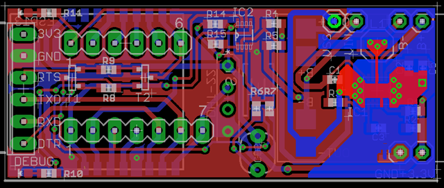
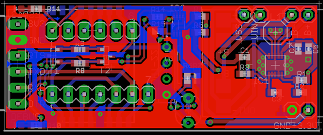
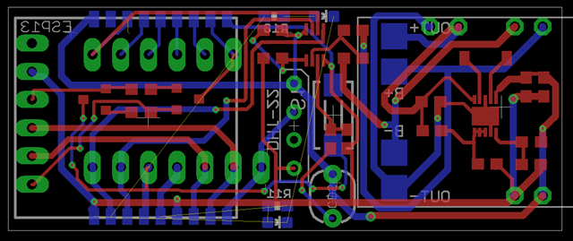
さて、Eagle の勉強をかねて、ESP8266 でPCBを作っているのですが、だいぶできてきました。
現在のところ、以下のような感じになっています。前回と違うのは、CDS のセンサーに分圧抵抗を入れて、1V 化したものをADC で計測しています。当初半固定抵抗を入れようと思っていたのですが、個体差には目をつぶることにして、安さを追求しました。

CDS は計測してみると、強い光を当てると、抵抗値が150オームくらいから、真っ暗にすると5Mオームくらいまで変動します。

分圧抵抗は以下のサイトが便利でした。
 ちなみに、nodemcu の回路のADC は、以下のようになっています。220k と 100k で分圧して1Vを作って計測しているようです。

電圧と、抵抗値を入れると出てくるサイトもあって、上記は以下のように入れると出てきます。

いろいろあって便利ですね。電卓で計算するより便利なので活用しています。
さて、前置きが長くなりましたが、 UART を挿しておけば自動的にファームウェアを書きかえれるモードにする方法です。
nodemucu は、回路図があって参考になります。以下のような回路です。
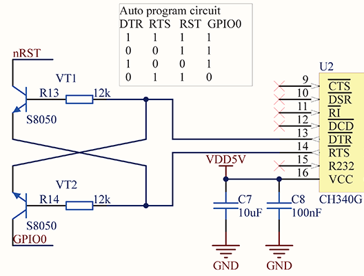
この回路は、RTS も使っているので、DTR のみというわけにはいきません。自分の持っているUART は RST は出ているんですが、ピンの横から出ていて直接挿すには、改造しないといけません。
DTR付のCP2102 をゲット
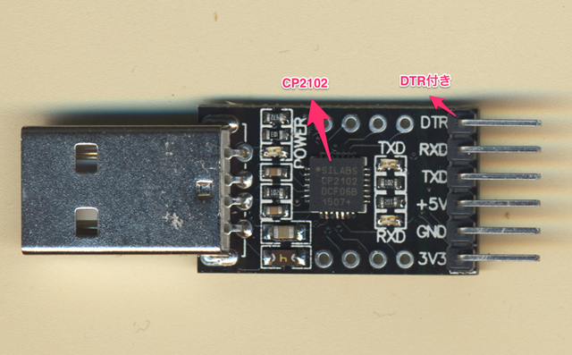
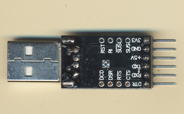
安くて、便利に使っているので2つ持っています。DTR だけでやるには以下のようにやれば良さそうなのですが、具体的な抵抗値と、コンデンサの値が良くわかりません。トランジスタは、PNP 形であれば良さそうです。
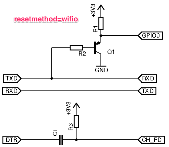
CH_PD は ESP13 や WROOM-02でいえば、EN ピンで普段は10k くらいでプルアップしている抵抗です。なので、R1 と R3 は10K程度でよいということはわかるのですが、R2 が良くわかりません。また、C1 はどのくらいの容量が良いのかも不明です。
プログラムを書き込みモードにする原理は、起動時にGPIO0 PinがGND に落ちていればいいので、R2 は10K 程度でよいのではと考えています。CH_PD にコンデンサを挟む原理は、再起動させる働きがあると理解すればよいのでしょうか?
一番シンプルな回路として、以下があります。ダイオードとコンデンサだけで、構成された回路です。
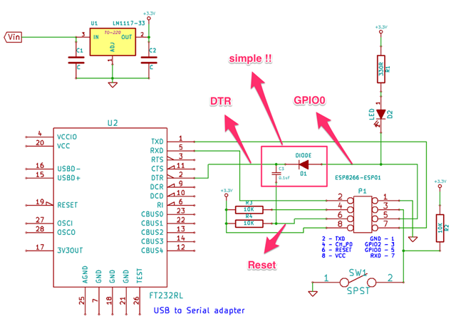
これが動作するのであれば、今回採用したいと思っています。
で、試してみました。手持ちには、1uf と 0.01uf しかないので、1uf で試しました。どうやら、これで書き込みモードになるようです。1uf だと30回の内、11回が成功し19回は失敗しました。3分の1の成功率です。もう少し、精度があがればいいのですが。
0.1uf だとちゃんと動くのかどうかは不明です。
コンデンサの数を並列に2,3と増やすと100%成功しますが、シリアルからコンソールを開くと、100%Boot せず、リセットをかけてもだめです。動いているときにシリアルを開いてもシステムが止まります。
どっかに0.1uf ないか探してみます。
ありましたが、1uF が一番成績が良かったです。
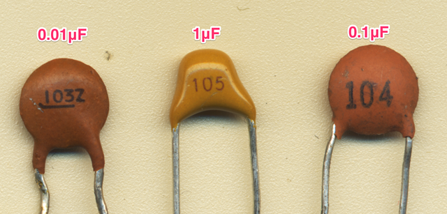
成功するときは、以下のようになります。
esptool v0.4.5 - (c) 2014 Ch. Klippel <ck@atelier-klippel.de>
    setting board to ck
    setting baudrate from 115200 to 115200
    setting port from /dev/tty.usbserial to /dev/cu.SLAB_USBtoUART
    setting address from 0x00000000 to 0x00000000
    espcomm_upload_file
    stat /var/folders/9c/0bsgxjzx63s7xhc_zz12jyp40000gn/T/build8239373840747412004.tmp/sample_FSA3357_adc_Select.cpp.bin success
opening port /dev/cu.SLAB_USBtoUART at 115200
    tcgetattr
    tcsetattr
    serial open
opening bootloader
resetting board
trying to connect
    setting character timeout 0
    done
    setting character timeout 1
    done
    espcomm_send_command: sending command header
    espcomm_send_command: sending command payload
trying to connect
    setting character timeout 0
    done
    setting character timeout 1
    done
    espcomm_send_command: sending command header
    espcomm_send_command: sending command payload
    espcomm_send_command: receiving 2 bytes of data
    espcomm_send_command: receiving 2 bytes of data
    espcomm_send_command: receiving 2 bytes of data
    espcomm_send_command: receiving 2 bytes of data
    espcomm_send_command: receiving 2 bytes of data
    espcomm_send_command: receiving 2 bytes of data
    espcomm_send_command: receiving 2 bytes of data
    espcomm_send_command: receiving 2 bytes of data
    espcomm_open
Uploading 297360 bytes from /var/folders/9c/0bsgxjzx63s7xhc_zz12jyp40000gn/T/build8239373840747412004.tmp/sample_FSA3357_adc_Select.cpp.bin to flash at 0x00000000
    erasing flash
    size: 048990 address: 000000
    first_sector_index: 0
    total_sector_count: 73
    head_sector_count: 16
    adjusted_sector_count: 57
    adjusted_size: 039000
    espcomm_send_command: sending command header
    espcomm_send_command: sending command payload
    setting timeout 10000
    setting character timeout 100
    done
    setting timeout 1
    setting character timeout 1
    done
    espcomm_send_command: receiving 2 bytes of data
    writing flash
...................................................................................................................................................................................................................................................................................................
starting app without reboot
    espcomm_send_command: sending command header
    espcomm_send_command: sending command payload
    espcomm_send_command: receiving 2 bytes of data
closing bootloader
失敗するときは、以下のよう。
esptool v0.4.5 - (c) 2014 Ch. Klippel <ck@atelier-klippel.de>
    setting board to ck
    setting baudrate from 115200 to 115200
    setting port from /dev/tty.usbserial to /dev/cu.SLAB_USBtoUART
    setting address from 0x00000000 to 0x00000000
    espcomm_upload_file
    stat /var/folders/9c/0bsgxjzx63s7xhc_zz12jyp40000gn/T/build8239373840747412004.tmp/sample_FSA3357_adc_Select.cpp.bin success
opening port /dev/cu.SLAB_USBtoUART at 115200
    tcgetattr
    tcsetattr
    serial open
opening bootloader
resetting board
trying to connect
    setting character timeout 0
    done
    setting character timeout 1
    done
    espcomm_send_command: sending command header
    espcomm_send_command: sending command payload
trying to connect
    setting character timeout 0
    done
    setting character timeout 1
    done
    espcomm_send_command: sending command header
    espcomm_send_command: sending command payload
trying to connect
    setting character timeout 0
    done
    setting character timeout 1
    done
    espcomm_send_command: sending command header
    espcomm_send_command: sending command payload
resetting board
trying to connect
    setting character timeout 0
    done
    setting character timeout 1
    done
    espcomm_send_command: sending command header
    espcomm_send_command: sending command payload
    serialport_receive_C0: 3E instead of C0
trying to connect
    setting character timeout 0
    done
    setting character timeout 1
    done
    espcomm_send_command: sending command header
    espcomm_send_command: sending command payload
trying to connect
    setting character timeout 0
    done
    setting character timeout 1
    done
    espcomm_send_command: sending command header
    espcomm_send_command: sending command payload
resetting board
trying to connect
    setting character timeout 0
    done
    setting character timeout 1
    done
    espcomm_send_command: sending command header
    espcomm_send_command: sending command payload
trying to connect
    setting character timeout 0
    done
    setting character timeout 1
    done
    espcomm_send_command: sending command header
    espcomm_send_command: sending command payload
trying to connect
    setting character timeout 0
    done
    setting character timeout 1
    done
    espcomm_send_command: sending command header
    espcomm_send_command: sending command payload
    serialport_receive_C0: 41 instead of C0
warning: espcomm_sync failed
error: espcomm_open failed
違う方法を模索しますか。まず、nodemcu でも採用されているNPNトランジスタを2つと抵抗2つを使ったもの。
自分のUART には、RTS があるのですがピンから出して配線。NPN トランジスタは、以下の左から2番目の2SC945を2つ使いました。たぶん、かなりの年代モノでジャンク箱にあったものです。
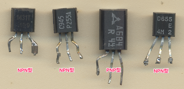
抵抗は、手持ちの適当なもの5.5k と 6.7k をつけました。当初、IDE (arduino に ESP8266 を組み込んだもの)からは、反応がなく「うーん、これもだめなの?」と思っていましたが、設定を以下のようにいじったら問題なくいけました。
---- esp8266/hardware/esp8266/1.6.5-947-*****/boards.txt
##############################################################
generic.name=Generic ESP8266 Module

generic.upload.tool=esptool
generic.upload.speed=115200
generic.upload.resetmethod=nodemcu
generic.upload.maximum_size=434160
generic.upload.maximum_data_size=81920
generic.upload.wait_for_upload_port=true
generic.serial.disableDTR=false
generic.serial.disableRTS=false
::
アプリケーションを再起動しないと駄目なようです。設定しても反映されないというなぜに陥りました。
設定が反映されているかどうかは、書き込み時の冒頭の赤い部分に出る以下で見分けがつきます。
esptool v0.4.6 - (c) 2014 Ch. Klippel <ck@atelier-klippel.de>
    setting board to nodemcu★
    setting baudrate from 115200 to 115200
    setting port from /dev/tty.usbserial to /dev/cu.SLAB_USBtoUART
    setting address from 0x00000000 to 0x00000000
    espcomm_upload_file
    stat /var/folders/9c/0bsgxjzx63s7xhc_zz12jyp40000gn/T/build6222680945723527651.tmp/sample_FSA3357_adc_Select.cpp.bin success
opening port /dev/cu.SLAB_USBtoUART at 115200
    tcgetattr
    tcsetattr
    serial open
esptool-ck は現時点で最新の0.4.6に入れ替えておきました。
とにかく、これでリセットボタンや、GPIO0 をGND に落としたり、スイッチをつけている場合はそれを押さなくてもよいよいになります。
今回の組み込みには、RTS を使わないDTRだけを使ったものにしたいと思いますので、PNPとコンデンサを使ったものをなんとか成功させたいです。一度、組み込んだのですがうまく動作しなくて。もしかしたら、この設定が反映されてないかもしれないので、もう一度組み込んでみます。
やっぱりだめでした。うーん。作者が言っているやつなのになぁー。
